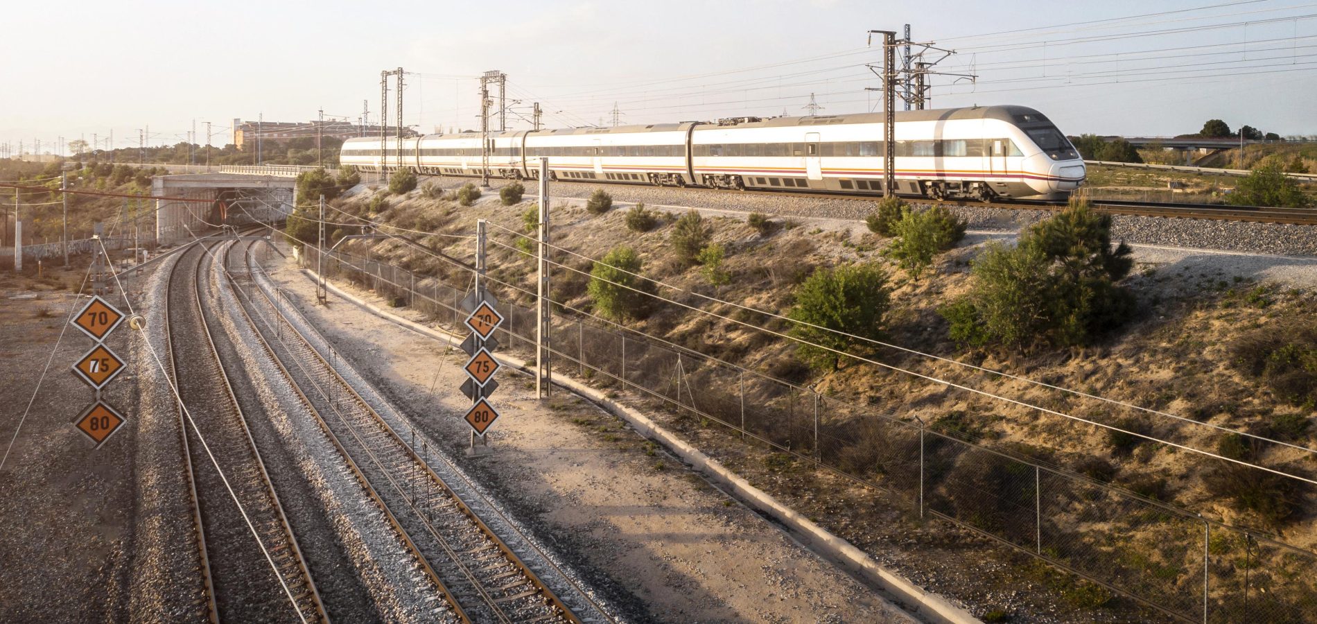
Detailed Rail Track Design And Analysis In One Application
A comprehensive software solution that streamlines the design of all your rail projects, including metro, light rail, commuter rail, and high-speed rail. Optimize your projects by automating the design and management of tracks, stations, and yards, resulting in substantial efficiency gains while saving you valuable time.
WHAT IS OPENRAIL DESIGNER?
OpenRail Designer introduces a new, comprehensive modeling environment for streamlined project delivery of rail network assets. This environment unifies design and construction from concept through commissioning and completion.
CAPABILITIES
- Add real-world digital context
You can bring real-world settings to your project by gathering context data quickly from a variety of sources, such as point clouds, 3D reality meshes, terrain data, images, and geospatial information. Clearly understand existing conditions and accelerate design modeling workflows and integrate geospatial information to ensure that models are precisely geospatially located. - Streamline collaboration across teams
Enable project information sharing across teams, locations, and disciplines with precision and security. - Visualize designs
Experience your designs in real time with constraint-driven templates, a context sensitive intuitive interface, and dynamic 3D modeling. Visualize the design at any time and on demand within the modeling workflow. No translations, software, or special workflow process is needed. And share realistic visualizations with the public and stakeholders to gather feedback, improve public engagements, and speed project approvals.
ADVANCE YOUR BIM WORKFLOWS
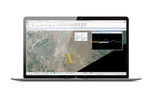
OpenRail Designer enables you to easily export digital deliverables, including IFC, to support industry BIM workflows. You can use Item Types to include component attribution for a more efficient, data-rich BIM deliverable. Easily advance your BIM workflows in a digital twin authoring environment while supporting the creation of all traditional and digital design deliverables.
CREATE HORIZONTAL AND VERTICAL ALIGNMENTS
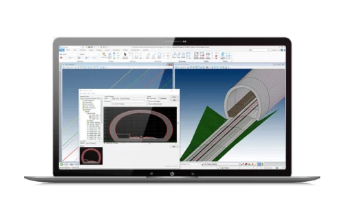
Use object-oriented coordinate geometry and alignment design capabilities that provide intelligent updating as you quickly create precision horizontal and vertical alignments. Use elevation profiles to display surface information, as well as vertical alignments associated with horizontal alignments.
Technical Capabilities
- Integrate data with OpenRail ConceptStation, MicroStation, ProjectWise, OpenBridge Modeler, OpenBuildings Designer, and other Bentley applications
- Support for managed workspaces
- Works across references files
- Include other engineering data (e.g. drainage) as referencing it to the DGN model
- Utilize an unlimited number of federated reference files
- Create and edit CAD elements
- Read and write to DGN and DWG files
- Supports design history
- Apply digital signatures using industry-standard encryption
- Secure digital rights definition for reviewing, printing, and editing
- Supports multiple raster formats
- Supports PostScript and HPGL2/RTL printing
- Use AccuDraw and AccuSnap navigation tools
- Track annotation
- Contour maps
- Import and analyze point-cloud data
- Merge surfaces automatically
- Update surface data dynamically
- Create intelligent, data-rich and lightweight terrain models
- No need for secondary terrain analysis to represent the terrain display. Includes context sensitive re-symbolization for triangles, contours, linear features, slope vectors, color code for slopes, elevation banding, and aspect
- Create terrain models from a variety of import sources
- Reality models
- 3D graphical data automatically using graphicalfilters
- ASCII/text data
- Legacy data formats of InRoads, GEOPAK, and MX
- Point clouds
- LandXML
- LiDAR data: ASCII and LAS
- USGS digital elevation model data
- Aerial data
- Raster files
- Ensure live, federated, and intelligent terrain models when stored as a DGN element
- Maintain terrain models through the preservation of relationships to source data
- Ensure correct entry with undo/redo capabilities
- Standardize displays via element templates
- Use across multiple disciplines via reference files in a comprehensive modeling environment
- Re-symbolization of display across multiple disciplines using a comprehensive modeling environment
- Control maximum length of triangles
- Control boundary conditions
- Create complex and clipped terrain models
- Interrogate the intelligent data rich 3D models
- Support for different features types including but not limited to boundaries, holes, voids, breaklines, inferred breaklines, and random points
- Model intelligent 3D real-world civil features (ditches, curbs, trees, and culverts)
- Context-sensitive intelligent editing of features
- Dynamic editing for
- Extend, trim, and intersect features
- Insert, move, and delete vertices
- Delete, partially delete, break, or join features
- Manage large LiDAR datasets
- Exclude non-DTM features from triangulation
- Control density of points on linear features for optimal surface presentation
- Display cut and fill delineation
- View and edit feature properties
- Contour smoothing
- Major, minor, and depression contours
- Automatic and manual contour labelling
- Model multiple design scenarios
- Edit designs dynamically
- Automatic model updates driven by design intent
- Design time visualization with automatic material assignments
- Undo/redo capabilities
- Interactively interrogate federated 3D models with dynamic cross sections
- Manage 2D/3D models and display representation
- Rule-based superelevation control of the model
- Use enhanced clipping and point controls
- Integrate and utilize CAD graphical elements in the model
- Create model reports dynamically
- Generate plan ready cross sections
- Utilize WYSIWYG features – control display of cross sections by simply turning on/off reference files
- Adheres to regional design standards
- Edit designs dynamically
- Blend horizontal and vertical geometry with 3D topography and typical sections
- Assign component control points to existing or designed features and geometry, controlling horizontal and/or vertical location
- Assign automatic overrides
- View plan, 3D model, profile, and cross section interactively
- Provides heads-up dynamic, interactive parametric design
- Level of detail user definable output
- Surface priority definable by target aliasing
- Transition among disparate templates
- Apply exceptions for bridges, voids, and special end conditions
- Clip model capability
- Edit stations dynamically
- Apply superelevation text tables, customizable calculations, or AASHTO standards
- Allows dynamic editing of superelevation
- Assists problem resolution through intelligent color coding of transitions, and super runout
- Component meshes provide direct volumetrics from the 3D model based on level of detail
- Reflect edits automatically in quantities and volumes
- Control component display via rules
- 3D modeling
- Create 3D utility model relative to topography and alignments
- Support interconnected network of pipes, curved pipes, channels, culverts, manholes, pumps, catch basins, and inlets
- Create associative and dynamic model-based designs
- Create storm, sanitary, or combined hydraulic networks
- Build utility models directly from survey data
- Identify graphics as utilities and drape relative to DTM
- Display all network and utility objects in sections and profiles
- Display as realistic 3D models for effective collaboration
- Identify conflicts among utility elements as well as among utilities and other 3D data
- Label all attributions in any view or include in user-defined reports
- Create user-defined attributes for any required data
- Draw 3D models of utility structures as full 3D shapes for easy clash detection
- Hydraulic design and analysis
- Analyze and design using industry-standard theorems such as Mannings, Colebrook-White, Bernouli, and continuity equations
- Analyze and design based upon HEC 22, FHWA, HDS 5, 10, 13, Rational Method, Wallingford Procedure, and regression equations
- Analyze and design using steady state gradually varied flow, and run simulations using unsteady state time-varying flow
- Compute Tc using methods such as TR-55, HEC-22, and Kinematic Wave
- Compute losses using methods such as SCS CN, Green and Ampt, Horton, Initial, and Constant Rate
- Compute runoff using methods such as Rational, Modified Rational, ILSAX, SCS, and Unit Hydrograph
- Use demand and demographic tables
- Supports infiltration, population, peaking factors, and land usage
- Compute or specify flows
- Define custom intensity-duration-frequency tables
- Generate drainage queries and customized reports
- Color code based upon queries or styles
- Calculate pond volumes
- Create input and output hydrographs
- Design inlet and outlet control structures
- Use PondMaker for inflow/ storage/outflow optimization
- Walk/drive through interactively or along a defined path or corridor
- Visualize paths through the project relative to design control by offsets and vehicle speeds
- Predefined materials applied to components enabling realistic rendering
- Position sun for geographically defined locations to ensure realistic shadow patterns
- Animate vehicles in traffic lanes without additional software
- Populate 3D objects along linear paths and within designated areas
- Apply traffic paint striping plans to the 3D model
- Use sample vehicle library and plantings
- Image draping on DTM or 3D objects
- MicroStation®-based rendering
- Real-life textures
- Lighting effects
- Elevation and perspectives
- Creation of fly-throughs and animations
- Creation of 3D PDFs
- Support for engineering data, point cloud, reality meshes
- Seamless integration with LumenRT for real-time, immersive presentations
- Solar and shading analysis
- Live documentation capable
- Automate project delivery process with drafting and drawing preparation tools
- User definable annotation tools for plan, profile, and section labeling
- Extract sections, drawings, and reports directly from completed 3D model
- Automate sheet generation for plans, profiles, and cross sections
- Select from more than 550 included report formats
- Modify included reports easily in any text or XML editor
- Provide standard reports for bridges, superelevation, clearances, data collection, geometry, sections, DTM, legal descriptions, design, visibility, and more
- Compute volumes by surface to surface (triangulated surface comparison)
- Compute volumes by 3D objects
- Export directly to machine guidance
- Supports iModel creation (includes 2D and 3D geometry and business data)
- Support industry standards, such as LandXML
- Export alignments, surfaces, and other pertinent design information to other systems via XML
- Generate PDFs and 3D PDFs
- Direct plotting
- Integrate with Google Earth
- Support for rail geometry definitions: Clothoid, Cubic Parabola, Bi-quadratic Parabola, Bloss, Sinusoid, and Cosine
- Support for rail transitions defined transition length or the spiral constant
- Single, Double, Diamond Crossings, Single Slip, Double Slip
- Built in Libraries; Austria, Germany (heavy and light rail), Holland, India, Italy, Russia, South Africa, Spain, Switzerland, United Kingdom,, United States, and Canada
- Custom libraries can be defined
- Turnout application on curves, turnout bending
- Rule based application, automatic healing of geometry and connections
- Easy design of complex connections and geometries with civil geometry
- Least squares method to calculate best-fit alignments
- Dynamic regression analysis
- Automatic sorting of point readings
- Horizontal and vertical regression
- Curvature diagram to help users identify curves, tangents, and spirals
- Convert rail readings to centreline, calculate existing vertical and cant
- Easy selection tools for regression points both on plan and curvature view
- Automatic placement of spirals
- Speed tables, speed assignment for different sections of the track
- Speed transitions
- Alternative speed selection; commuter rail, freight rail, express…
- Automatic or manual creation, based on geometry and design standards
- Cant calculation; equilibrium cant, applied cant, cant deficiency, rate of change of applied cant, rate of change of cant deficiency, and cant gradient
- Cant diagram
- Automatic identification of design problems
- Virtual transitions
- Precise rail calculations based on curvature and cant
- Track widening application
- Rail joints
- Sleeper placement, long sleepers on turnout areas
- Custom train definitions, with articulation and bogie definitions
- Swept envelope using curvature and cant values
- 3D representation of envelope for clash detection
- 2D projection of swept envelope
- Design rules and geometry based calculations to determine foundation locations
- Span equation and span lookup tables
- 3, 4, 5 span overlap definitions. Insulated, uninsulated overlaps and natural sections
- Simple and stitched wire runs. Precise contact, catenary and dropper wire height and length calculations
- Cant and geometry based stagger calculations
- Return and feeder wire placement
- Parametric 3D cells for structure calculations
- Moment calculations for mast and foundation selection
- Foundations, masts, single or multiple cantilever sets, and portal definitions
- Automated placement of additional OLE equipment; end wire tensioning, mid wire tensioning, jumpers, anchorage…
- Full 3D model with structures and wires
- Schematic 2D representation of OLE system
- Profile drawings and quantity reports
- Cross sections with dimension and quantity annotation for manufacturing
- Rail signal library with asset tags
- 2D and 3D representation of signals
- Signal sighting analysis
Our STAAD.Pro Customers

